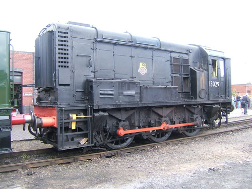
English Electric 350 h.p. diesel electric shunter 13029 (later Class 08) at Tyseley Locomotive Works. Around 1990, this was the first diesel I was passed to drive and was very handy for shunting early in the morning when the 'steamers' were still 'brewing-up'.
History
Class: 08/0
Built: BR 1958-1962.
Engine: English Electric 6-cyl 6KT of 400bhp (315kW).
Weight: 49 tonnes.
Brake force: 19 tonnes.
Maximum tractive effort: 35000lb (156kN).
Power/control equipment: English Electric Two EE505 traction motors. Double reduction gear drive.
BR Route availability: 5.
Maximum speed: 15 mph, except certain 20 mph.
Fuel: 668 gallons.
Pre-start checks
Check axlebox dipsticks for oil level and replenish if necessary. Oil coupling rods.
Open battery box on left side of locomotive and close battery switch. Open battery box on rightside of locomotive and close battery switch, additionally visually check the condition of the contacts on starter contactor.
Check main fuel tank gauge. There should be at least 50 gallons, to avoid sediment being drawn from the main tank. Enter cab and ensure handbrake applied. Check service tank fuel gauge. There should be at least 20 gallons, to avoid sediment being drawn into the engine fuel system. As necessary, operate the hand fuel transfer pump to replenish the service tank. Insert master key. Operate the hand pump on the rear wall of the cab for 30 - 45 seconds to pressurise the oil system.
Insert the master key and move to the non-locking 'EO' (Engine Only) position. Further operate the key to the non-locking 'start' position and hold in this position until the engine is firing correctly. Allow the key to return to the 'EO'position and then move it into the 'off' position, in which the battery will be re-charged and the main compressor will start. Wait until the main reservoir pressure (indicated on the duplex brake gauge) has reached 70 psi. Move the straight air brake application valve into the down (applied) position. Full brake pressure should be indicated on the duplex gauge.
The DSD is checked by placing the master direction controller in forward or backward, pressing the foot treadle and moving the driver's application valve for the straight air brake into the up (release) position. On the duplex gauge, the brake needle should fall to zero, indicating brake release. Release the DSD treadle and observe that, after a delay of a few seconds, the brake is automatically applied.
To release the brake after the test, place the driver's valve in the 'brake applied' position, depress the DSD treadle and move the driver's valve back to the release position.
To release the handbrake, partially apply the straight air brake then wind off the brake. Ensure the direction switch is set correctly for the intended movement, lookout to ensure it is safe to move, sound the horn and move to power controller into first notch. Pause at the first notch position and ensure that the motor contactor has energised (audible 'clump' from the control panel), then gently advance the power controller as necessary for the movement, checking the total generator amps as shown on the current meter.
Britsh Rail Mechanical Department, York training notes
These can be viewed, printed or downloaded here.
They comprise 9 pages:-
1. General Layout Diagram 200
2. Cooling Water System Description
3. Cooling Water System Diagram 201
4. Lubrication System Description
5. Lubrication System Diagram 202
6. Fuel System Description
7. Fuel System Diagram 203
8. Air and Vacuum System Description
9. Air and Vacuum System Diagram 204
